
Standby Generator Transfer Warnings: Separating Wiring, Transfer Equipment, and Controller Faults
July 12, 2026
A low-voltage transfer warning can point to several different failure locations. Voltage behavior under the correct operating conditions is often the key to locating the true fault.
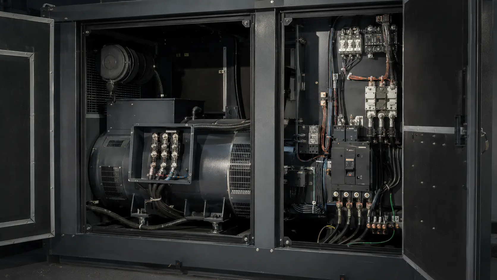
Automatic standby systems depend on more than engine operation and line-voltage switching. Low-voltage conductors carry start commands, transfer status, battery-derived control power, and supervisory signals between the generator and automatic transfer equipment. A warning associated with that circuit can originate in the field wiring, the transfer equipment, the generator controller, or the power and grounding shared by those components.
The most reliable diagnosis follows the signal from its source to its destination and observes how it behaves connected, disconnected, at rest, during cranking, while running, and during transfer.
BEGIN WITH THE CORRECT SYSTEM STATE
A voltage measurement is meaningful only if the technician records the system state. A conductor may be expected to carry one value with the generator merely powered, another while the engine is running, and a different state when the transfer switch changes position. Comparing a measurement to the wrong expected condition can lead directly to unnecessary part replacement.
ISOLATE WITHOUT LOSING THE CIRCUIT LOGIC
- Confirm battery voltage and the integrity of controller power and ground
- Inspect terminations, conductor continuity, polarity, and pin fit
- Measure the signal at both ends of the interconnecting circuit
- Compare open-circuit voltage with voltage under load
- Observe the signal during start, run, exercise, and transfer sequences
- Use the manufacturer’s schematic and diagnostic sequence for the exact controller and transfer configuration
WHY OPEN-CIRCUIT VOLTAGE CAN MISLEAD
A digital meter can display a plausible voltage through a high-resistance connection or an internally damaged output because the meter itself draws very little current. Once the circuit is connected and required to operate a real input or output, the voltage may collapse. Loaded testing—performed without exceeding the circuit’s rating—helps distinguish available control power from a ghost or high-resistance reading.
Conversely, disconnecting a circuit may remove the controller’s reference or feedback path. The expected disconnected reading must therefore come from the correct service documentation, not assumption.
A DEFENSIBLE REPAIR DIAGNOSIS
The diagnosis should identify the test condition, expected value, measured value, isolation step, and result at each point in the circuit. When the wiring and transfer-side components perform correctly but the controller cannot provide, receive, or interpret the specified signal, the evidence can support a controller fault. The same disciplined sequence can also prevent a good controller from being blamed for a damaged conductor, poor ground, or transfer-equipment problem.
NEED A FORENSIC ELECTRICAL ENGINEER?